
Description
LNWR 1878 Chain brake


CLARK AND WEBB’S BRAKE. (From Engineering 1878)
In our number of the 18th ult. we gave a two-page engraving showing the application of the Clark and Webb brake to a guard’s van on the London and North-Western Railway, while with our present number we give another two-page engraving showing the brake gear us applied to one of the now six-wheeled carriages on the same line. The Clark chain brake has already been fully dealt with in our pages, and we do not pro-pose here to discuss either its merits or demerits, but simply to describe it as improved in its details by Mr. Webb, and as adopted by the London and North-Western Railway Company, that company having at the end of the past year upwards of 2500 vehicles which had either been fitted with the brake, or with chains for the trans-mission of the brake power.
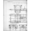
Our engravings, we may add, show not only the brake gear, but also the under-frames of the very fine new passenger stock which the London and North-Western Railway Company have of late been putting upon their line. Referring first to the two-page engraving which we published on the 18th ult., it will be seen that the van has six wheels, but that four wheels only are fitted with brake blocks, while it will also be noticed that these blocks are not applied by the Clark and Webb arrangement, but by hand only.
The guard’s van has, in fact, an ordinary hand-screw brake, the chain gear which it carries applying the brake blocks on other carriages only. The brake blocks of the van, however, are hung on Mr. Webb’s plan, and as will be seen the arrangement is a very effective and simple one. The Clark and Webb brake is actuated by the middle axle of the van, that axle having a cast-iron drum fixed on it as shown in Figs. 1 and 2 of our engraving of the 18th ult. Supported by hangers from the frame (see Figs. 1, 2, and 6) is a short shaft carrying a drum which is in a line with that on the middle axle, and also a barrel on which the chain is wound. The hanger, which supports one end of this short shaft, is stiffened by a diagonal stay, as shown in Fig. 1, but the hanger carrying the other end swings on a fulcrum fixed to the frame, as shown in Fig. G, and it thus allows the drum on the short shaft to be brought into contact with or removed from the drum fixed on the centre axle. As shown also in Figs. 1, 2, and 6, this swinging hanger is connected by a link with the short arm of a bell-crank lever having its fulcrum on the frame, and the longer horizontal arm of which carries a heavy weight, this weight being connected by a chain, as shown in Figs. 1 and 7, with a hand lever on the guard’s van. At the handle end of this last- mentioned lever is a detent or trip lever, as shown in Fig. 8, this trip lever serving to keep the weight on the bell-crank lever raised and the friction drums thus out of contact with each other.
If, however, this trip lever is pulled out of the way either by the guard in the van or by a communication cord which runs through the train, the hand lever is released, the weight arm of the bell-crank lever falls, and the friction drum on the chain barrel shaft is brought into contact with that fixed on the middle axle, the result being that the chains are wound up on the barrel, and the brakes of the adjacent carriage applied in the way we shall explain presently. By raising the weighted arm of the bell-crank lever the brake is, of course, released. The chain barrel, it will be noticed receives two chains, which are led off over the guide pulleys shown, to the opposite ends of the vehicle.
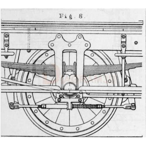
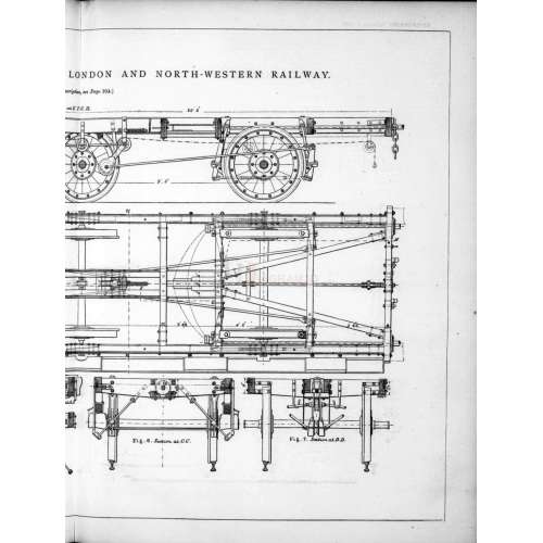
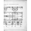
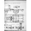
Turning now to the two-page engraving which we publish this week, it will be seen that on the carriages the brake is applied to four wheels only. The brake blocks, which are applied to both sides of the wheels, are of cast iron and are slung from the frames by links as shown in Figs. 1 and 5, the mode of suspension being such that the blocks can not only approach or recede from the wheels, but can also swivel on a vertical axis and thus adapt themselves to the tyres. Each block forms a fulcrum for an inclined brake lever, the lower ends of the lever for each pair of blocks being connected outside the wheels by a link as shown in the view, Fig; 8, which we give on the present page.
This link, it will be noticed, passes through a lug on the horn-plate stay, and is provided with a ferrule bearing against one side of this lug, and a helical spring bearing against the other, the effect of this arrangement being to carry the blocks clear of the wheels when the brake is released, and at the same time to allow of a mutual adjustment of the blocks when the pressure is applied. the inner ends of one inclined lever for each wheel is jointed to the frame, while the inner ends of the other lover is in the case of one pair of wheels (that on the right-hand side of our two-page engraving) coupled by links to the axis of a chain pulley mounted between the lower ends of a pair of weighted links, as shown in Figs. 1 and 7, the upper end of these links being jointed to hangers between which another chain pulley works. These hangers are in their turn jointed to the frame and are pressed in one direction by a helical spring as represented in Fig. 1, while the pin forming the axis of the chain-pulley between them is connected by links with the brake levers of the other pair of wheels. The path of the chain is shown by a strong dotted line in Fig. 1, and can be readily traced.
The result of a strain upon the chain is, as will be seen, to raise the weighted pulley and bring all the brake blocks into contact with the wheels. the arrangement of the brake rigging we have described has been designed by Mr. Webb, and it is one which answers its purpose admirably, giving a good distribution of the strain upon the blocks, while its details have been exceedingly well worked out.