
Description
LNWR 1904 Wolverton Carriage Works
-500x500.jpg)
-500x500.jpg)
-100x100.jpg)
-100x100.jpg)
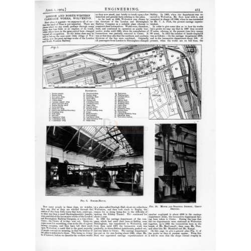
LONDON AND NORTH WESTERN CARRIAGE WORKS, WOLVERTON.
How often it appears —we suppose to all of us— that the hand of Time is not impartial. There are places which we can recall, perhaps through many years, that hear little or no impress of its touch, while others have in the same period been changed beyond all recognition. To the latter class may be said to belong the once quiet little village of Wolverton, now the great carriage works of the London and North Western Railway.
How many people in these days, we wonder, have any idea as they are whirled through the station of this busy little town that here, years ago, in what was then a small Buckinghamshire hamlet, were established the locomotive works of the London and Birmingham Railway Company, at a time when Crewe — the Crewe of today — was not. Sixty-six years count for something, even in the life of a great railway company, and they have left their mark upon Wolverton, a mark that to the great majority of people conveys no meaning, in that the history of the place is unknown to them. This being so, it may be of interest, before we describe the modern works as they now stand, just briefly to touch upon a few historical and general facts relating to the place. As far back as 1838, Wolverton was chosen by the directors of the London and Birmingham Railway Company as a suitable place whereat to construct their locomotives. Works were, therefore, built, and continued in operation as purely locomotive works until 1865, when the manufacture of locomotives was partially removed to Crewe. It was at this time also that the northern and southern divisions of the line were combined. Originally all passengers from London to Birmingham changed at a place called Denbigh Hall, about six miles from Wolverton, and then took coach to Rugby, the reason for so doing being due to the difficulty of making the Kilsley Tunnel.
This continued for about a year. In 1850 the carriage department of the company, which had until then been at Saltley, near Birmingham, was transferred to Wolverton, and from then until 1877 the locomotive work was gradually, in three distinct instalments, pushed out, and was taken to Crewe. The carriage department was put on its own footing about 1860, when Mr. Bore was appointed carriage superintendent at Saltley.
In 1865, when the department was removed to Wolverton, Mr. Bore went with it, and remained in charge till 1886, when he was succeeded by Mr. C. A. Park, the present carriage superintendent. In order to give some idea as to how the works have grown we may say that in 1887 they covered 67 acres, whereas at the present time they occupy 80 acres. In 1872 the number of hands employed was as follows In the carriage department 2000, and in the locomotive department about 500. At present, when the works are on full time, the number employed is about 4500 in the carriage department alone, the locomotive department having been taken to Crewe. During the time that the two departments were stationed at Wolverton together, up to 1865 the locomotives were in the hands of Mr. MacConnell; then came Mr. Peet, and after him Mr. Mumford and Mr. Kampf. On this page we give a general plan (Fig. 1) of the works as they at present appear.
From this it will be seen that the shops extend roughly in the form of the letter L- The part of the works with which we are at present more particularly interested is that which has been recently constructed, for it has all been designed and laid out on modern lines by Mr. C. A. Park, (the present carriage superintendent, and all the different shops are electrically driven. They are well arranged for carrying out the highest class of work economically. The arrangement of the electric power station will be seen on reference to Figs. 2, 3, 4, and 5, page 457. The following shops are driven from it:— The saw mill, the carpenters shop, the smiths shop, the fitting and turning shop, the bogie and underframe shop, the parcel-cart shop, the wheel and axle shop, the crane-lifting shops, and the finishing - shops. Of these the lifting-shop, the wheel and axle shop, the carriage-repairing shop, and the finishing-shops have been built within the last five or six years ; the paint shop is also new, though no power is required in it.
Commencing with the boiler-house, an internal view of which is given in Fig. 6, page 453, it will be seen that there are four boilers in all, two of which are rather larger in diameter than the others. The two larger ones are 30 ft. long by 8 ft. 0 in. in diameter, and the two small ones are 30 ft long by 7 ft. 0 in. in diameter. They are worked at a pressure of 180 lb. per square inch, and the two larger ones are fitted with Musgrave super-heaters in which the steam is heated to 400 deg. Fa. At the back of the boilers there is a Green economiser, containing 448 pipes, the scraper gear of which is driven by a 4-horse-power motor. The boilers and pipes are lagged with Keenan’s patent non-conducting composition, which is coloured and varnished. Two Weir feed-pumps, 5 1/2 in. by 7 1/2 in., with a stroke of 15 in., are used.
Owing to the fact that the ordinary water is very hard, a Stanhope water-softening apparatus is employed. As will be seen by the illustration, the boilers are automatically stoked, small slack being used as fuel. The coal is brought to the power station in bottom-hopper trucks, and is dropped into the coal-bunkers. From there it is taken by a Bennis chain conveyor, and carried along a trough over the hoppers, into which it is discharged through shoots. The ashes are taken away by a similar chain conveyor, and delivered into a wagon by means of a Bennis ash-hoist. The automatic stokers are also of the Bennis pattern, with hollow fire-bars, and steam forced-draught is employed. A Bennis patent automatic steam-regulator is also used, which, by means of a diaphragm in connection with the steam pipe, controls the damper gear, and so regulates the steam pressure, which is 160 lb. per square inch at the engine stop-valve. A view of the engine-room is shown in Fig. 7, page 478, from which a good idea of the general arrangement may be obtained. There are two Belliss and Morcom triple-expansion condensing engines, of 290 brake horse-power each, which run at 420 revolutions per minute. They are direct-coupled to two 200-kilowatt six-pole Westinghouse compound - wound generators, which supply current at 250 volts pressure. There are also two Belliss and Morcom triple expansion condensing engines of 580 brake horse-power each, which run at 360 revolutions per minute, and one Bumstead and Chandler engine ; the two former being coupled direct to two 400-kilowatt 8-pole compound wound Westinghouse generators, and the latter to a 430-kilowatt Lancashire Dynamo and Motor Company’s compound-wound generator ; this machine being used for lighting the yard and any shops that might be working at night time. It can also be used for driving machines during holiday times. All the dynamos have a voltage of 250. The condenser pit, which may be seen in Fig. 8, contains two Admiralty-pattern Wheeler surface condensers, which have 1400 square feet of cooling surface.
There is an oil-separator by Messrs. Craven Brothers, of Manchester, and a Lancashire Dynamo and Motor Company’s I-horse-power motor-driven oil-pump. The steam-pipes are lagged with silicate cotton, under blued Russian iron casing, and the joints are covered with nickel-plated bands. This work was done by Messrs. Jones and Horsfield, of Manchester. The floor of the engine-room is covered with red tiles with an ornamental bordering round the walls and engine beds. This forms a very neat and pleasing finish to the whole.
The switchboard has 13 panels, and is shown in Fig. 8, page 468. The first five panels, counting from the left, are generator panels; then come six feeder panels, one recording ammeter panel, and one blank panel. The power and lighting currents are at present taken on the same bus-bars. The panels are composed of Italian marble. Each generator has a recording ammeter and a wattmeter. The bus-bars are of aluminium, and the cables are painted red, blue, and black, to represent positive, negative, and equaliser currents respectively. Opening out of the engine-room is the switchboard attendant’s office, and a small stores containing oil, filters, etc. The engine-room has a 6-ton hand-driven overhead travelling crane by Messrs. Craven Brothers, and also a Blackman motor-driven fan for ventilation.
The yard is lighted during working hours by means of arc lamps fixed upon posts, which posts also carry two incandescent lamps each, the latter for use in the night time, after work-hours, in order to enable the workmen to find their way about. The general lighting of the shops is by means of arc lamps; in a few of the shops inverted arcs arc used, but as a rule the ordinary pattern is found to give a better light. In the painting and repair shops incandescents only are used, pitched at 15 ft. centres, incandescents are also used over the vices and benches, and one to each machine.
There is a distribution board in each shop. The machinery in the various shops is motor driven, but in the majority of cases the motors drive the shafting in sections, in order to save having a large stock of spare armatures; these motors are usually of 10 or 20 horse-power. In the case of the larger machines, and of most of those in the saw-mill, there is a motor on each machine. The usual methods of driving when shafting is employed are clearly shown in Figs. 9 and 10, pages 460 and 453 ; in the latter case the motors are placed on a platform about the level of the counter-shafting. The platform is provided with a ladder, so that the motor can be easily got at for purposes of cleaning and lubrication. Electric traversers by Messrs. Craven Brothers are used in the shops, and these have overhead trolley feed. The winch gear is put in by means of a clutch, and one lever works the traverse and winch gear. The overhead cranes are all electric, and are of the throe-motor type. They were supplied by Messrs. Craven Brothers, and are shown in Fig. 11, which is a view of the lifting-shop.
In addition to electric power, hydraulic and pneumatic tools are largely employed in the works, the pneumatic being in the majority. Pneumatic hammers are used in the underframe and bogie-shops, pneumatic spanners and bolt-cutters in the whoel-shop, and pneumatic drills and saws largely in the body and repair-shop. Some of the lighter hoists are also of the pneumatic type, and a large number of 1-ton and 30-cwt. air-lifts are used in connection with the machines. Portable pneumatic jacks are also used in the lifting, repair, and body shops.
In the smithy there are four batteries of drop-hammers supplied by Messrs. Brett and Co., of Coventry, and these range from 8 cwt. to 20 cwt. The brake work, draw-gear, and much of the work in connection with the underframes is forged under these hammers. Fig. 13 is a view of the inside of the saw-mill.
A good deal of electric welding is done in these works, the current being supplied by a generator separately excited The generator is driven by a belt from an Alley and MacLellan high-speed engine. The transformer is placed underneath the welder itself, which latter is on Thompson’s system; the electric welder may lie seen in Fig. 12.
In large works like those we have just described it is of great importance that some efficient means of cleaning the carriage cushions should be adopted. This is very thoroughly done by means of a vacuum cleaner, supplied by the British Vacuum Cleaner Company. It is driven by a continuous-current motor, and is practically an air-pump with two suction hoses which have nozzles at the end. When these latter are passed over a cushion or carpet, all the dust is sucked out into a receiver, which can he emptied at intervals.
To anyone who has not seen this apparatus in action, the amount of dirt and dust that one of these machines will extract from a cushion appears almost impossible.