This website uses cookies. By continuing you permit us to deploy cookies, as detailed in our Privacy Policy.  Accept
 

Description

Construction

  • These parts are made by assembling the supplied layers in a SmartFrame. Before they were assembled the cardboard layers were sealed. In this case an artists fixative was used. . The layers were then placed in position in the SmartFrame using PVA glue and allowed to set. The parts were then sprayed with a base coat. When the paint was dry the parts were detached from the Smartframe and further paint was applied to give the final result.
  • The next stage of assembly is to construct the inner partitions and roof struts. The partitions and roof struts have been sprayed black and then detached from their layer. The MDF floor was detached from the SmartFrame. Fine slots in the floor used to position the partitions were cleared of any residual debris using a razor saw. This coach has a guards lookout. The guards lookout front panel was assembled in the SmartFrame and has already been painted. glazing was then attached to this component before positioning it in the MDF floor. The partitions were placed in position and attached to the floor with PVA glue. Finally the longitudinal roof struts were positioned and glued into position.
  • Using a 10mm knitting needle on a flexible surface to roll the tumblehome into a coach side
  • This image shows the sides being attached prior to putting on the roof of this model. Note the clever usage of hair bands to hold the pieces in position while the adhesive sets. The bands are strong enough to hold the supporting steel rule against the side being attached without damaging the fine detail or paint.
  • This image shows a Great Northern Railway four compartment third class coach in the course of construction. The glazing at the guards end is being assembled. The next procedure will be to add the coach end (with glazing) and the guards look-out or "ducket". The interior compartments have been left plain and painted black. In this case the modeller has chosen to keep the bodywork separate from the floor, using the floor provided as a jig for assembly purposes. At a later stage the floor will be attached but made removable for maintenance. All images are supplied by customers.
  • The completed kit, incorporating some additional roof detail (lamps and torpedo vents) which are not part of the kit from Diagram3D.
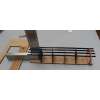
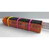
  • Images showing the construction of one of our kits.